Tersa EDA
Tersa EDARF / analog

Analog- und HF-Schaltungen, überall abgestimmt.

Tersa EDA ist eine App für Mobilgeräte und Desktop, um Schaltpläne zu erstellen, Simulationen auszuführen, Bauteile abzustimmen und HF-Messungen zu prüfen.

SchaltpläneAC / transientS-ParameterSmith-DiagrammBauteil-Tuner
HF und Smith-Diagramm
Schaltplaneditor
Bauteil-Tuner
Run / Live

Produktnachweis

Für echte Schaltungsarbeit entwickelt.

Erstelle einen Schaltplan, wähle eine Analyse, füge Messungen hinzu und stimme Werte ab, ohne das Gerät zu wechseln.

Schaltplaneditor
Schaltplaneditor

Schaltplaneditor

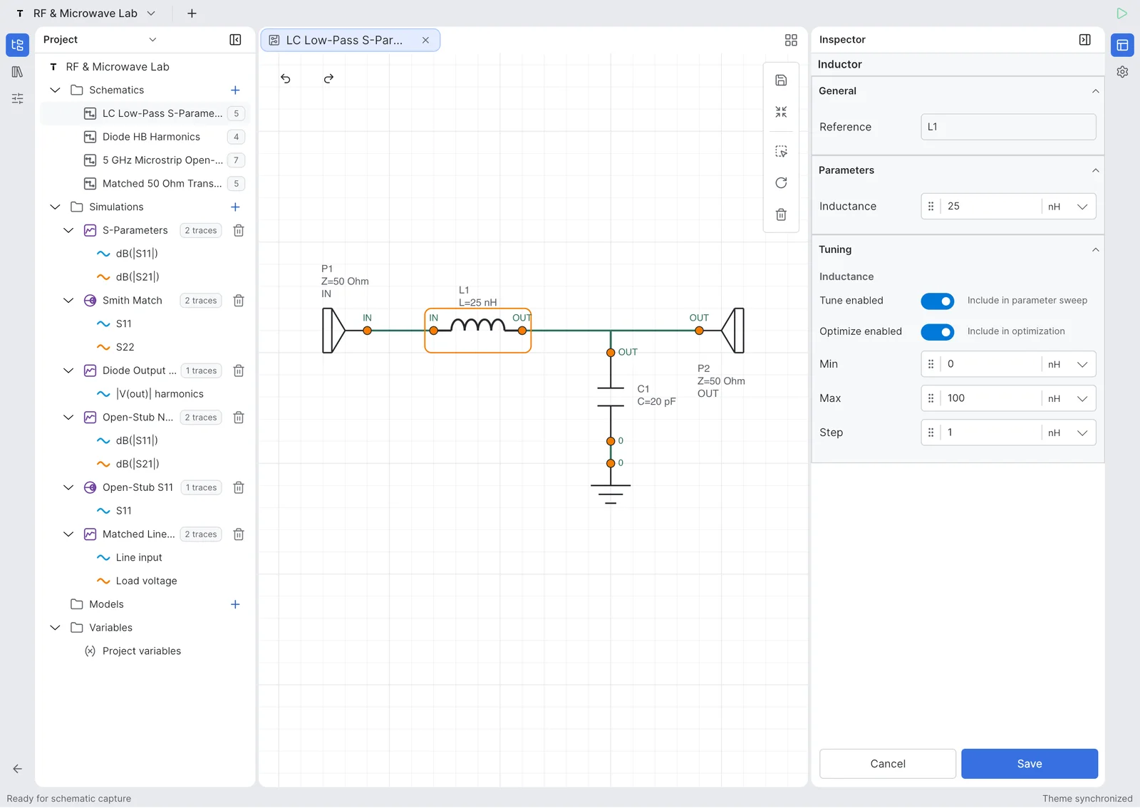
Zeichne Analog- und HF-Schaltungen mit Ports, Bauteilen, Netznamen und touchfreundlicher Bearbeitung.

Messungen
Messungen und Plots

Messungen und Plots

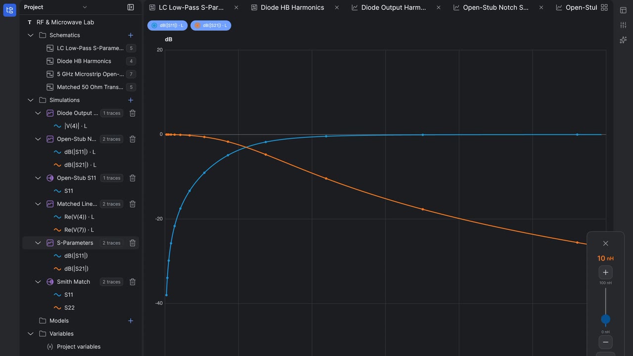
Prüfe Kurven, Marker, Frequenzgänge und abgeleitete Messungen.

HF
HF und Smith-Diagramm

HF und Smith-Diagramm

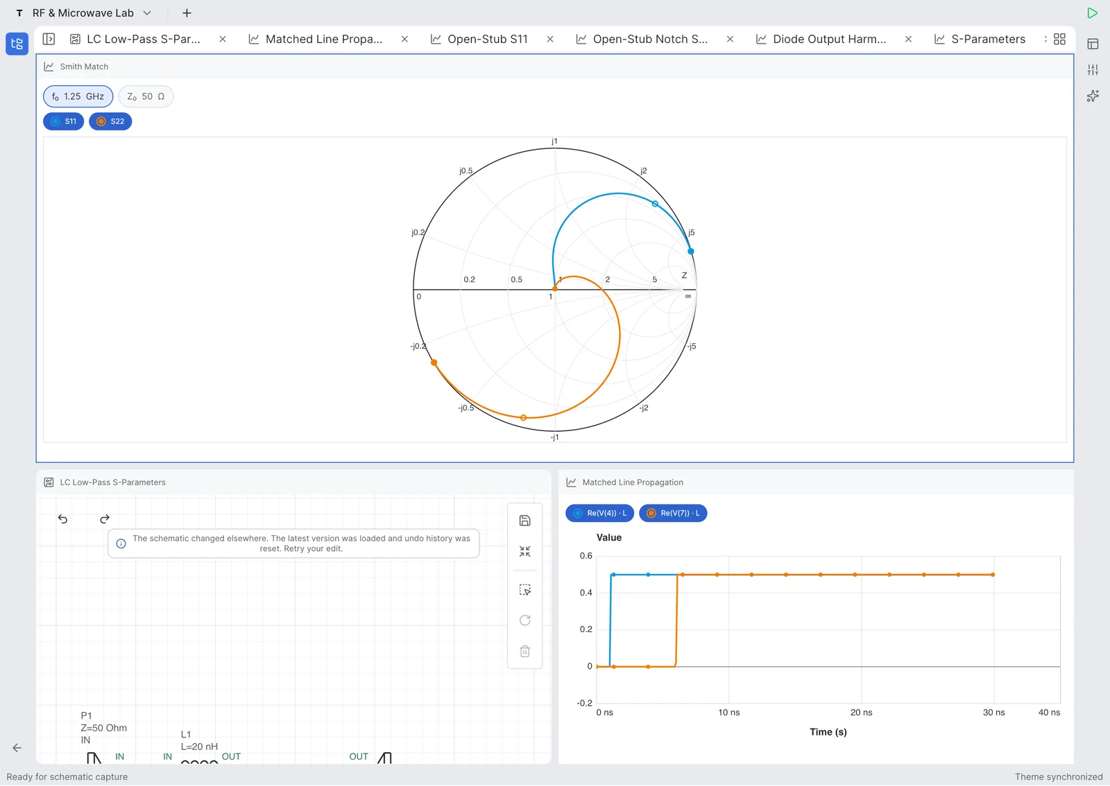
Analysiere S-Parameter, Return Loss, Insertion Loss, Impedanz und Smith-Diagramm-Trajektorien.

Updated July 27, 2026

Tersa EDA answers

What is Tersa EDA?

Tersa EDA is an RF and analog circuit simulation workspace for engineers, students, and hardware teams who need a focused schematic-to-measurement flow. It combines schematic capture, SPICE-compatible analysis setup, plots, RF measurements, Smith chart inspection, and component tuning in one product surface. The goal is not to replace large desktop EDA suites. The product is designed for quick experiments, tablet review, mobile debugging, and focused circuit tuning when the important question is how the response changes after a component value, port, or measurement is adjusted.

What RF measurements does it support?

Tersa EDA presents RF results around practical measurements: S11, S21, S12, S22, return loss, insertion loss, gain, stability-oriented traces, frequency markers, and Smith chart trajectories. The workflow starts from the schematic, adds ports and analysis settings, then keeps the plot and tuner connected to the circuit. This makes it useful for filters, matching networks, resonators, small-signal experiments, and quick RF review where the designer needs to compare traces instead of exporting data between separate tools.

What does the 500 MHz LPF example show?

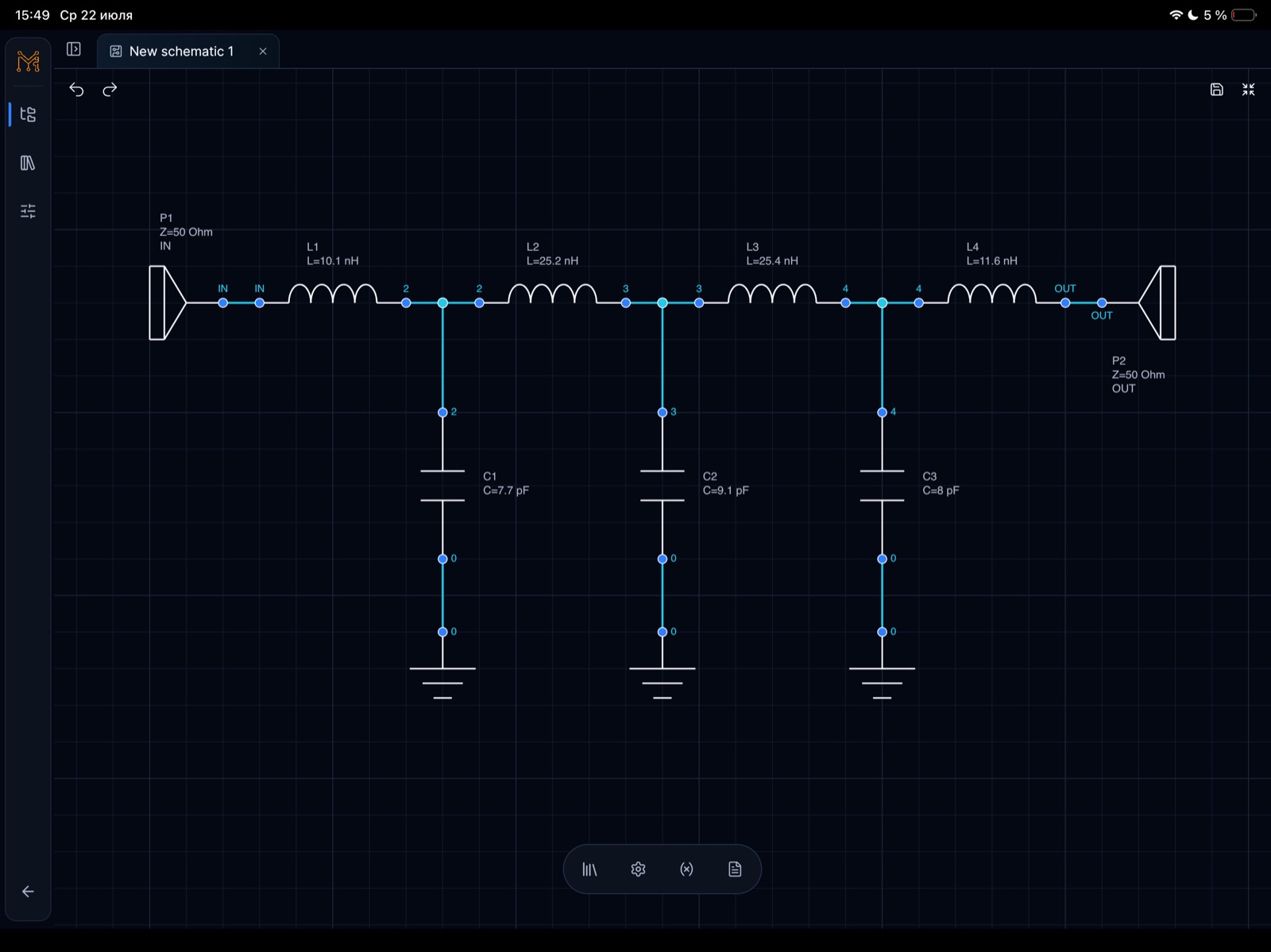
The 500 MHz low-pass filter example demonstrates a complete RF workflow on iPad. It shows a 50 ohm ladder filter with series inductors, shunt capacitors, input and output ports, S-parameter simulation to 1 GHz, insertion loss, return loss, and component tuning. The blue S21 trace shows passband behavior and roll-off, while the green S11 and S22 traces help inspect matching. The tuning sweep makes cutoff movement visible as capacitor and inductor values change around the target frequency.

Funktionen

Vom Schaltplan zur Messung.

Touchfreundlicher Schaltplaneditor

Erstelle Schaltungen mit Bauteilen, Ports, Labels und wiederverwendbaren Blättern auf Mobilgerät, Tablet oder Desktop.

Simulationsergebnisse

Führe AC-, Transienten- und HF-Analysen mit klaren Plots, Markern und Kurvensteuerung aus.

HF-Werkzeuge

Prüfe S-Parameter, Return Loss, Insertion Loss, Smith-Diagramme, Gain und Stabilitätsmetriken.

Bauteil-Tuner

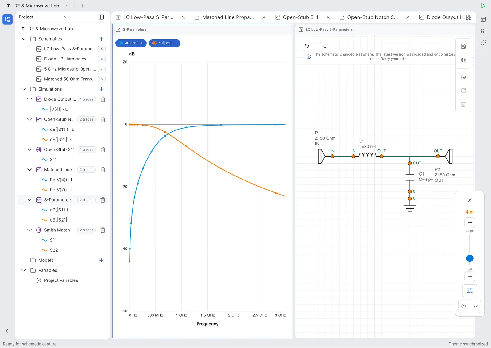
Stimme Bauteilwerte ab und sieh sofort, wie sich die Schaltungsantwort verändert.

Workflow

Vom Schaltplan zur Erkenntnis.

Erstelle einen Schaltplan, wähle eine Analyse, füge Messungen hinzu und stimme Werte ab, ohne das Gerät zu wechseln.

01

Schaltung zeichnen

Bauteile platzieren, Netze verbinden und Ports definieren.

02

Analyse wählen

AC-, Transienten- oder HF-Simulationen ausführen.

03

Messungen hinzufügen

Spannungen, S-Parameter, Verluste und Marker plotten.

04

Werte abstimmen

Bauteile anpassen und Antworten vergleichen.

Product demos

Sieh echte RLC-Workflows auf iPhone und iPad.

Kurze Videos zeigen Schaltplanerstellung, Simulation, Messung und Live-Bauteil-Tuning in Tersa EDA.

Auf YouTube öffnen
iPhone shorts

Real-Time RLC Circuit Tuning on iPhone

Tune an RLC circuit directly on iPhone and watch the response update while component values change.

Auf YouTube öffnen
iPhone shorts

Building and Simulating an RLC Circuit on iPhone

Create an RLC schematic on iPhone, run simulation, and inspect the first measurement workflow.

Auf YouTube öffnen
iPad walkthroughs

Tuning RLC Resonance in Real Time on iPad

Use the iPad workspace to tune resonance and compare circuit response changes on a larger engineering canvas.

Auf YouTube öffnen
iPad walkthroughs

Building an RLC Resonator on iPad | Tersa EDA

Build an RLC resonator from scratch on iPad and move from schematic capture into analysis setup.

Auf YouTube öffnen

RF example

500 MHz low-pass filter example on iPad.

A concrete LPF case study built in Tersa EDA: schematic capture, 50 ohm ports, S-parameter simulation, insertion loss, return loss, and component tuning around a 500 MHz target.

Target

500 MHz LPF

Ports

50 ohm IN / OUT

Analysis

S-parameters to 1 GHz

Workflow

Schematic, plot, tuner

This example shows a lumped 500 MHz low-pass filter workflow, not a generic screenshot gallery. The circuit uses a ladder topology with 50 ohm input and output ports, series inductors, shunt capacitors, and RF measurements plotted from DC to 1 GHz.

The blue S21 trace shows the passband and roll-off, while the green S11/S22 traces help inspect matching and return loss. Tuning sweeps make cutoff movement visible as component values change.

500 MHz low-pass filter schematic with 50 ohm input and output ports, four inductors, and three shunt capacitors in Tersa EDA on iPad
500 MHz low-pass filter schematic on iPad. Schematic capture for a 50 ohm 500 MHz low-pass filter with L1-L4 series inductors and C1-C3 shunt capacitors.
S-parameter plot for a 500 MHz low-pass filter showing S21 passband and roll-off toward 1 GHz in Tersa EDA

500 MHz LPF S-parameter response

S-parameter response with S21 staying flat through the passband before the transition region toward 1 GHz.

Tunable parameter panel for a 500 MHz low-pass filter showing capacitor and inductor optimization ranges on iPad

500 MHz LPF tunable component parameters

Tuning ranges expose capacitor and inductor values so the cutoff behavior can be optimized directly from the schematic.

500 MHz low-pass filter tuning sweep with multiple S-parameter traces showing cutoff movement and stopband behavior

500 MHz LPF tuning sweep

A tuning sweep compares multiple S-parameter traces around the cutoff and stopband regions.

Tersa EDA project workspace showing a 500 MHz low-pass filter schematic and simulation plot on iPad

500 MHz LPF project workspace

The project workspace keeps the LPF schematic, simulation plot, variables, and tunable parameters in one engineering flow.

Return loss and insertion loss plot for a 500 MHz low-pass filter from 0 Hz to 1 GHz in Tersa EDA

500 MHz LPF return loss and insertion loss

Return loss and insertion loss traces make it possible to inspect passband fit and out-of-band rejection.

HF-Werkzeuge

Für HF-Experimente gebaut.

Tersa EDA kombiniert HF-fokussierte Messungen mit alltäglicher Analogsimulation: S-Parameter, Return Loss, Insertion Loss, Smith-Diagramm-Trajektorien, Gain, Stabilitätsfaktoren und Marker für Zielfrequenzen.

S11 / S21 / S12 / S22
Return Loss und Insertion Loss
Smith-Diagramm-Marker
Gain und Stabilitätsmetriken
Matching- und Tuning-Workflow
HF und Smith-Diagramm
SchaltplaneditorMessungen und Plots

Analog

Nützlich für alltägliche Analogschaltungen.

Nutze Tersa EDA für Filter, Teiler, Verstärker, Diodenschaltungen, RC-Transienten, Frequenzgänge und schnelle Was-wäre-wenn-Experimente.

AC-FrequenzgangTransiente WellenformenSpannungsmessungenBauteil-TuningBeispielschaltungen

Screenshots

Ein Workspace, der der Schaltung folgt.

Echte App-Screens für Projekte, Schaltplanbearbeitung, HF-Plots, Smith-Diagramm und Tuning.

Projekte

Projekte

Schaltplanliste

Schaltplanliste

Schaltplaneditor

Schaltplaneditor

Rechteckiger Plot

Rechteckiger Plot

Smith-Diagramm

Smith-Diagramm

Bauteil-Tuner

Bauteil-Tuner

Beta-Test

Tersa EDA ist jetzt im Beta-Test.

Wir laden Ingenieure, Studierende und HF/Analog-Teams ein, frühe Builds zu testen und uns zu sagen, was zuerst geschärft werden sollte.

Geplanter Beta-Release: etwa 5. August 2026.
Direkt mailen: hello@tersaeda.com

Sag uns, was du testen möchtest

Sende eine kurze Beta-Anfrage. Wir antworten von hello@tersaeda.com.

FAQ

Ist Tersa EDA ein PCB-Design-Tool?

Noch nicht. Tersa EDA konzentriert sich auf Schaltplanerfassung, Simulation, Messungen, Plots und Analog/HF-Tuning.

Ersetzt es ADS, AWR oder LTspice?

Nein. Es ist ein leichter Workspace für schnelle Experimente, mobile Prüfung und HF/Analog-Abstimmung.

Was kann ich simulieren?

Die ersten Versionen fokussieren Analogschaltungen, AC- und Transientenanalyse, S-Parameter, Smith-Diagramme und Bauteil-Tuning.

Ist es nur mobil?

Nein. Die Oberfläche ist für Mobilgerät, Tablet und Desktop ausgelegt.

Welchen Simulator-Workflow nutzt es?

Tersa EDA nutzt einen SPICE-compatible Workflow für Schaltungsanalyse.