01
What an S-parameter describes
An S-parameter describes how a traveling RF wave is reflected or transmitted at a network port. For a two-port device, the first index identifies the receiving port and the second identifies the excited port. S11 therefore measures the wave returning to port 1 when port 1 is excited, while S21 measures the wave reaching port 2 from that excitation. The values only make sense with the reference impedance and frequency sweep stated.
- S11 is a reflection coefficient at the input port
- S21 is forward transmission from port 1 to port 2
- S12 describes reverse transmission
- S22 describes reflection at the output port
02
How S11 becomes return loss
S11 is complex, so it contains magnitude and phase. Plots often show its magnitude in decibels as 20 log10(|S11|), which is normally zero or negative for a passive network. Return loss is commonly reported as the positive value -20 log10(|S11|). That sign convention causes many mistakes: an S11 trace at -20 dB corresponds to 20 dB return loss and about one percent reflected power.
- More-negative S11 magnitude means less reflected power
- S11 = -10 dB corresponds to 10 dB return loss
- Return loss is not the same quantity as insertion loss
- Always confirm whether a plot label shows S11 dB or positive return loss
03
How S21 relates to insertion loss and gain
S21 shows forward transmission. A passive filter with S21 near 0 dB in its passband transmits most available power, while a negative value indicates attenuation. Insertion loss is often written as -20 log10(|S21|), so an S21 magnitude of -1 dB corresponds to 1 dB insertion loss. An active network may produce positive S21 dB, which is forward gain rather than negative insertion loss.
- Use S21 to locate passband and stopband behavior
- A passive passband should be close to 0 dB, not above it
- The cutoff definition depends on the filter specification
- Positive S21 can be valid for an active device with gain
04
Read S11 and S21 together
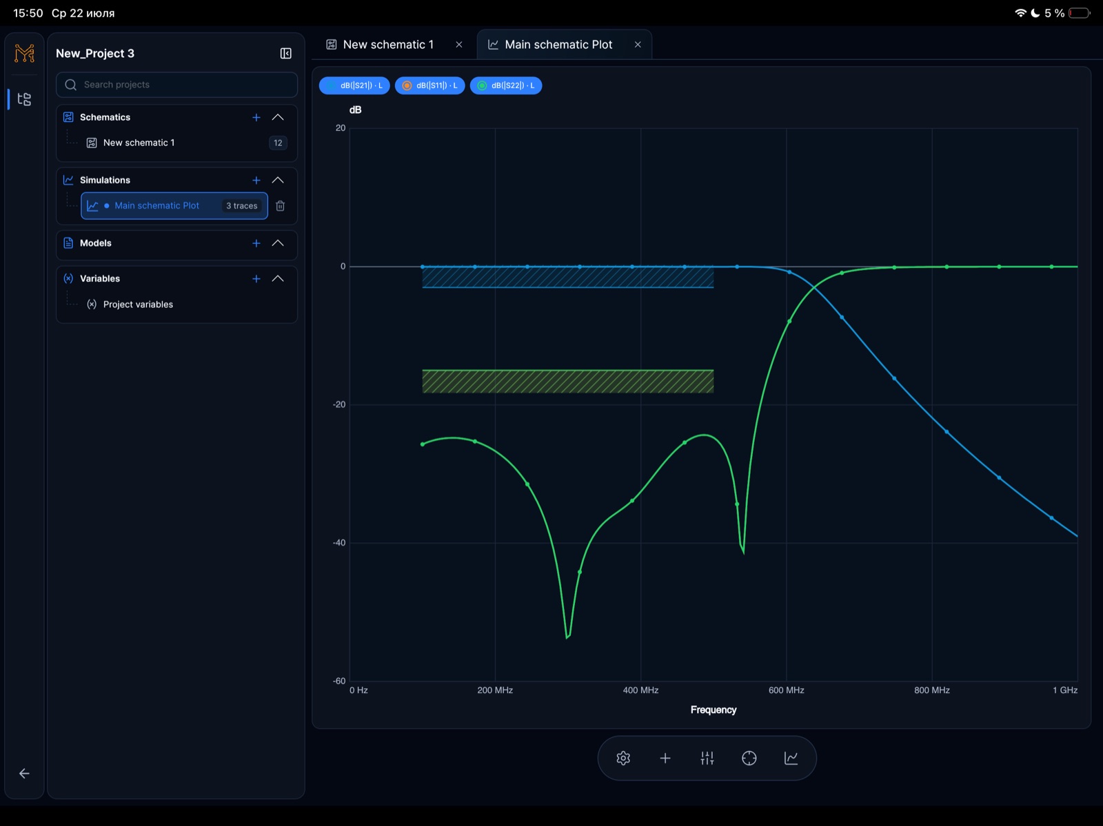
A filter decision is stronger when transmission and reflection are inspected together. A falling S21 trace shows that less power reaches the output, but it does not by itself say whether power is reflected, dissipated, or redistributed by loss and mismatch. S11 reveals the input match at the same frequencies. Place markers on both traces at the passband edge, design frequency, cutoff target, and critical stopband points before changing components.
- Check passband S21 and S11 at the same marker frequencies
- Separate mismatch loss from intended stopband rejection
- Compare the full sweep before and after tuning
- Record reference impedance, sweep limits, and marker values
Plot a Touchstone S1P or S2P file. Inspect S11 and, for a two-port file, S21 at the same frequency. The viewer reads supported files locally in your browser; nothing is uploaded.
05
What is a good S11 value?
A good S11 value is one that satisfies the matching requirement over the complete operating band. As a practical reading aid, S11 below -10 dB means less than ten percent of incident power is reflected, while S11 below -20 dB means about one percent is reflected. These are useful reference points, not universal pass/fail limits: filters, antennas, amplifiers, and measurement fixtures can require different return-loss targets.
- S11 of -10 dB equals 10 dB return loss
- S11 of -20 dB equals 20 dB return loss
- Judge the worst point across the required band
- Use the specification, not a generic threshold, for acceptance
06
Convert S11 to VSWR and reflected power
The linear reflection-coefficient magnitude is |Γ| = 10^(S11 dB / 20). Reflected power fraction is |Γ|², and VSWR is (1 + |Γ|) / (1 - |Γ|). For example, S11 = -10 dB gives |Γ| about 0.316, roughly ten percent reflected power, and VSWR about 1.92:1. Keeping the sign convention explicit prevents a negative S11 trace from being confused with positive return loss.
- Convert dB to linear magnitude before calculating VSWR
- Reflected power uses the square of |Γ|
- VSWR approaches 1:1 as the match improves
- Keep the same reference impedance when comparing results
Calculate reflection and VSWR on a Smith chart. If you know the complex load, enter its resistance R, reactance X and reference impedance Z0. This calculator starts from impedance, not an S11 dB value.
07
Measure insertion loss with S21
For a passive two-port network, place reference planes at the intended input and output, apply the same port impedance, and read S21 at the frequencies required by the specification. A measured S21 of -1.2 dB corresponds to 1.2 dB insertion loss. Use markers across the passband rather than one favorable point, and compare the result with S11 to distinguish intended attenuation from a poor input match.
- Define input and output reference planes
- Use the same port impedance as the design system
- Record minimum and maximum S21 across the passband
- Inspect S11 at the same marker frequencies
08
Try S11 and S21 on iPhone or iPad
Tersa is available for both devices. Use the illustrated 500 MHz low-pass filter as a starting point: recreate the shown network, set both ports to 50 Ω, and compare S11 and S21 over the same sweep. The example uses real Tersa captures; it is not a one-click project import. Exact response depends on the topology, values and models you enter.
- Start from the schematic and component values shown in the example
- Place S11 and S21 markers at the same passband and stopband frequencies
- Change one capacitor or inductor at a time, rerun, and compare the response
- Keep the same reference impedance and sweep when comparing traces
Follow the 500 MHz filter example. See the circuit and plots, then open the iPhone and iPad app from the example page.